Basic Button
How to make a button for FMCU
To setup the lab you will need a MCU that can connect to the internet we have had success with the ESP32 from seeed studio. The .ino can can be found here CODE
Note:
- The code is written for a button connected to 3.3V.
- If your button is instead connected to GND, update the following lines in the code:
- Line 62: change
PULLDOWNtoPULLUP:cpp pinMode(buttonPin, INPUT_PULLUP);- Line 112: change
HIGHtoLOW:cpp if (buttonState == LOW)
FMCU-fla
Clone the repo and update code to your needs or copy fla-fmcu.ino and create file called config.h.
Set your labs ID, SSID & Password
Create config.h file with the following lines and edit them accordingly.
// Your fablabs.io lab id
const char id[] = "";

#define WLAN_SSID ""    // Your wifi name
#define WLAN_PASS ""    // Your wifi password
the code
Here is the code that you can copy paste:
////////////////////////////////////////////////////////////////////////////////
// FMCU Button code
// By Fran Sanchez (The Beach Lab)
// January 2022
//
// IDE:
//   Arduino 2.0.0
// Platform:
//   esp32 2.0.5 - https://github.com/espressif/arduino-esp32
// Board:
//   XIAO_ESP32C3
// Libraries:
//   Adafruit_MQTT
////////////////////////////////////////////////////////////////////////////////

// Includes

#include <WiFi.h>
#include "Adafruit_MQTT.h"
#include "Adafruit_MQTT_Client.h"
//#include "config.h"
////** Your fablabs.io lab id
const char id[] = "";

#define WLAN_SSID ""    // Your wifi name
#define WLAN_PASS ""    // Your wifi password

////////////////////////////////////////////////////////////////////////////////

// Pinouts according to FabXAIO
// Modify to your needs

const int buttonPin = D7;   // the number of the pushbutton pin GPIO 10 ESP32
const int ledPin    = D6;   // the number of the LED pin  Internal LED

////////////////////////////////////////////////////////////////////////////////

int buttonState     = 0;    // variable for reading the pushbutton status

// MQTT Settings
#define AIO_SERVER      "fmcu.fablabs.io"

// Using port 8883 for MQTTS
#define AIO_SERVERPORT  1883

// MQTT Account Configuration
#define AIO_USERNAME    "fmcu"
#define AIO_KEY         "Push 1 Button"

// WiFiFlientSecure for SSL/TLS support
WiFiClient client;

// Setup the MQTT client class by passing in the WiFi client and MQTT server and login details.
Adafruit_MQTT_Client mqtt(&client, AIO_SERVER, AIO_SERVERPORT, AIO_USERNAME, AIO_KEY);

/****************************** Feeds ***************************************/

// Setup a feed with the id for publishing.
// Notice MQTT paths for AIO follow the form: <username>/feeds/<feedname>
Adafruit_MQTT_Publish alive = Adafruit_MQTT_Publish(&mqtt, "fmcu/id");

void setup()
{
  Serial.begin(9600);
  delay(100);

  pinMode(buttonPin, INPUT_PULLUP);
  pinMode(ledPin, OUTPUT);

// Connect to WiFi access point.
  Serial.println(); Serial.println();
  Serial.print("Connecting to ");
  Serial.println(WLAN_SSID);

  delay(1000);

WiFi.begin(WLAN_SSID, WLAN_PASS);

int retries = 0;
const int maxRetries = 20;

while (WiFi.status() != WL_CONNECTED && retries < maxRetries) {
  delay(500);
  Serial.print(".");
  blinkLED(); // Visual feedback
  retries++;
}

while (WiFi.status() != WL_CONNECTED) {
  Serial.println("WiFi not connected, retrying...");
  WiFi.disconnect(true);  // Optional: force disconnect first
  WiFi.begin(WLAN_SSID, WLAN_PASS);
  for (int i = 0; i < 20; i++) { // Try for 10s
    if (WiFi.status() == WL_CONNECTED) break;
    delay(500);
    Serial.print(".");
    blinkLED();
  }

  if (WiFi.status() == WL_CONNECTED) {
    Serial.println("\nWiFi connected!");
    Serial.print("IP address: "); Serial.println(WiFi.localIP());
    blinkLED(); // Confirm with LED
    break;
  } else {
    Serial.println("\nStill not connected. Retrying in 5 seconds...");
    for (int i = 0; i < 5; i++) {
      digitalWrite(ledPin, HIGH); delay(250);
      digitalWrite(ledPin, LOW); delay(250);
    }
    delay(2000); // Wait before retry
  }
}

}

void blinkLED(){
  for(int i = 0; i < 10; i++){
    digitalWrite(ledPin, HIGH);
    delay(50);
    digitalWrite(ledPin, LOW);
    delay(50);
  }
}

void loop()
{
  if (WiFi.status() != WL_CONNECTED){
    Serial.println("WiFi not connected....");
    blinkLED();
  } else{
    //Serial.println("Yes.");

    ////////////////////////////////////////
    // Publish to MQTT server
    // Ensure the connection to the MQTT server is alive (this will make the first
    // connection and automatically reconnect when disconnected).  See the MQTT_connect
    // function definition further below.
    MQTT_connect();
    buttonState = digitalRead(buttonPin);

    // check if the pushbutton is pressed. If it is, the buttonState is HIGH:
    if (buttonState == LOW) {
      // Now we can publish stuff!

      Serial.print(F("\nSending id "));
      Serial.print(id);
      Serial.print(F(" to fmcu feed..."));
      if (! alive.publish(id)) {
        Serial.println(F("Failed"));
      } else {
        Serial.println(F("OK!"));
        digitalWrite(ledPin, HIGH);
        delay(500);
      }
    } else {
      digitalWrite(ledPin, LOW);
    }
  }

  delay(100);
}

// Function to connect and reconnect as necessary to the MQTT server.
// Should be called in the loop function and it will take care if connecting.
void MQTT_connect() {
  int8_t ret;

  // Stop if already connected.
  if (mqtt.connected()) {
    return;
  }

  Serial.print("Connecting to MQTT... ");

  uint8_t retries = 3;
  while ((ret = mqtt.connect()) != 0) { // connect will return 0 for connected

    Serial.println(mqtt.connectErrorString(ret));
    Serial.println("Retrying MQTT connection in 5 seconds...");
    mqtt.disconnect();
    blinkLED();
    delay(5000);  // wait 5 seconds
    retries--;
    if (retries == 0) {
      // blink forever to indicate failure
      while (true) {
        blinkLED(); // Infinite blinking if failing here
      }
    }
  }

  Serial.println("MQTT Connected!");
  blinkLED();  // Indicate success blinks and stops blinkink
}
notes
- your lab idea witch you will find here press the total lab nr. Lab_ID
- On ESP32 pin is set to GPIO 10 if wanted this can be modified
In theory FMCU should work on any board. Below is a list of boards that have been tested and that need to be tested.
- [x]EXTRA Perfect with FABxiao try it out!
- [x] XIAO ESP32C3 works
- [x] raspberry Pi Pico works code need's to be adapted
- [ ] Arduino UNO with wifi shield not tested
- [ ] esp32 didn't work
- [ ]we have not tried ethernet cable at this point
workflow
below you will find a workflow chart to set up the FMCU
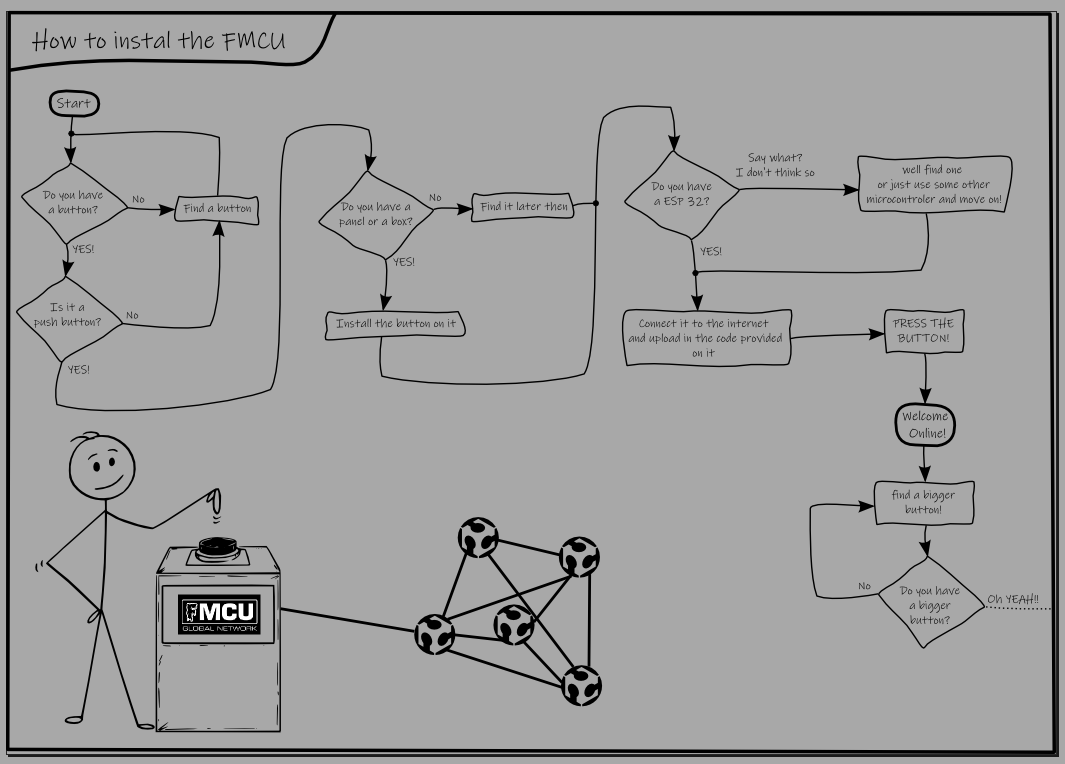
Good luck setting up your FMCU and let us know and share photos when your online!