Learn to use each of the machines on the micro lab cart!
Key Science Concept: Aerodynamic Forces
Four forces act upon a plane in the air: thrust, lift, gravity, and drag.
Planes’ designs must balance all of these forces. The shapes, sizes, and materials used for the wings, body, nose, and tail can all drastically affect the way a plane flies. How can we engineer a glider to take advantage of these forces?
In the Real World
: Iterative Prototyping
Engineers don’t create perfect designs on the first try.
They test, redesign, and retest their ideas again and again, making small changes each time based on their observations. This is called iterative prototyping, and it’s a key part of the engineering design process. Instead of thinking of lackluster designs as “failures,” think of them as rough drafts of a finished product. Each one is a step closer to success.
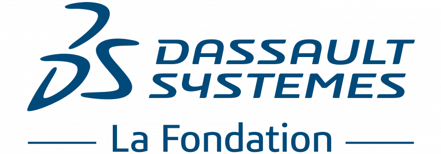
Key Fabrication Concept: Parametric Design
A smart way to tweak digital designs.
Instead of creating a new CAD model from scratch each time they need to make a change, engineers use something called parametric modeling. This means they assign adjustable variables to each dimension of their design instead of values. These labels can be single variables, like x in a math equation, or they can be a function of a variable, like x+6 or x/2. We could even make them a function of each other: wing width could equal body length - tail width. Parametric design allows engineers to scale an entire model up or down or make small tweaks to a single part.
A. Design your parts.
B. Export your file.
A. Connect laser cutter.
B. Import & format design file.
C. Configure cut settings.
D. Prepare laser cutter.
E. Run cut job.
F. Remove pieces.
A. Prepare the machine:
B. Prepare cardstock:
C. Configure cut settings:
D. Run job:
E. Remove pieces:
A. Load filament:
B. Load print file:
C. Remove finished print(s):
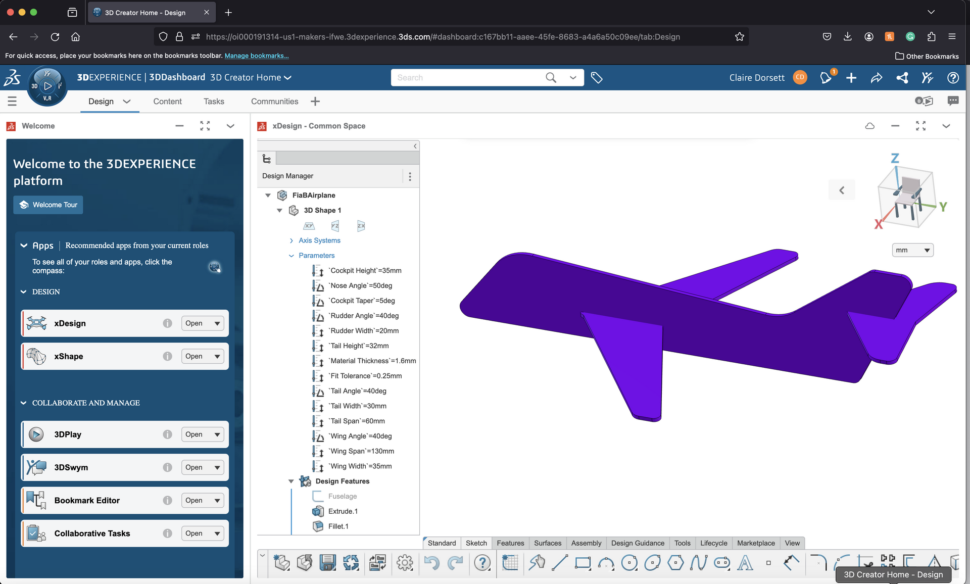
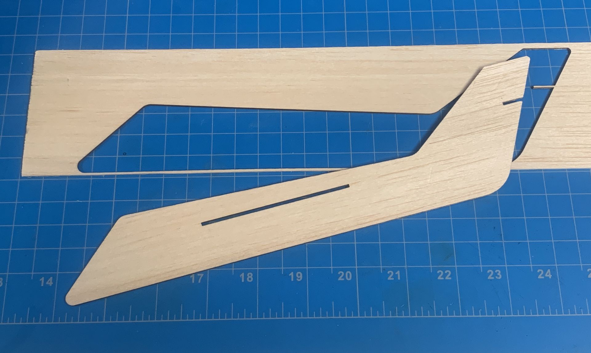
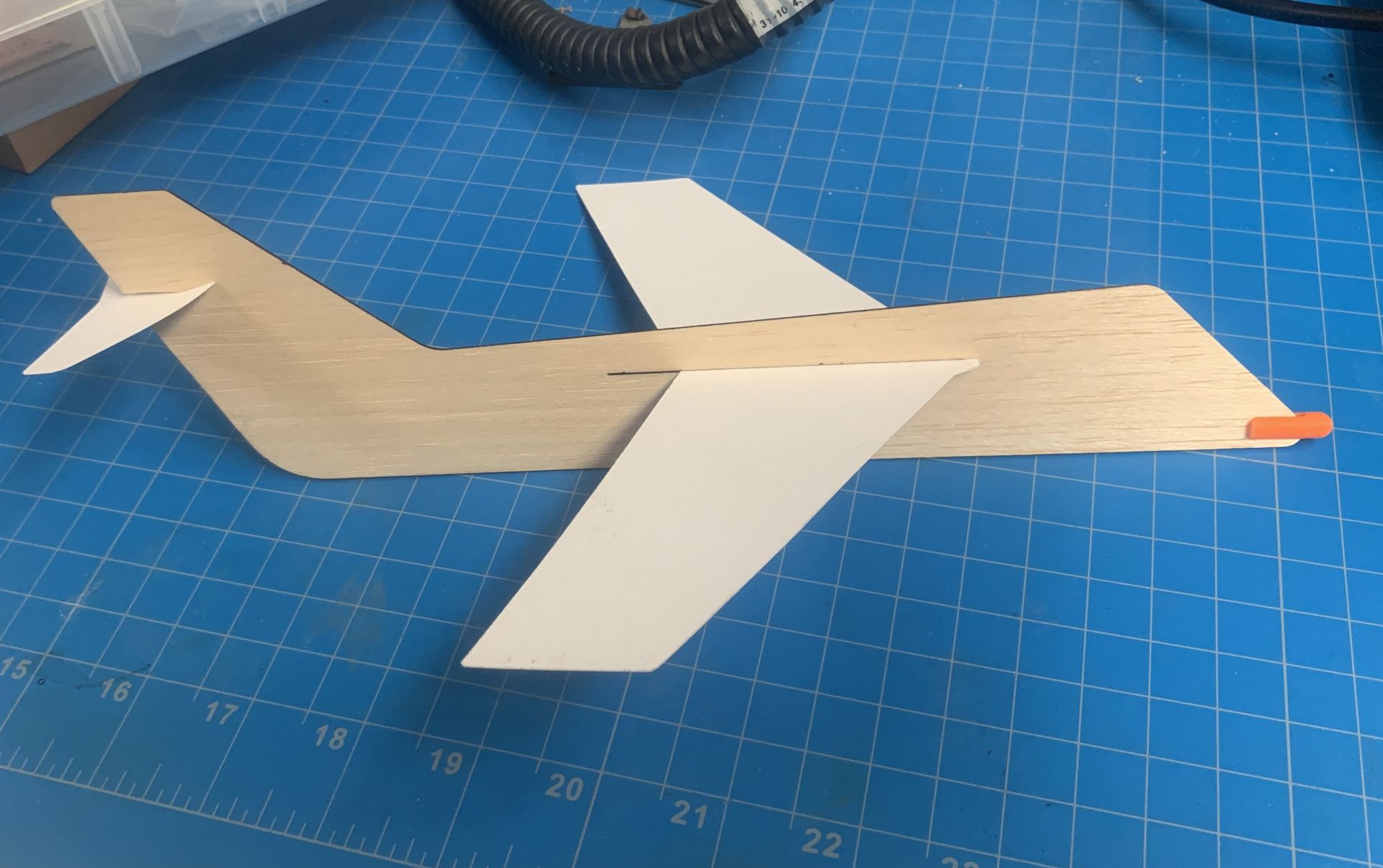
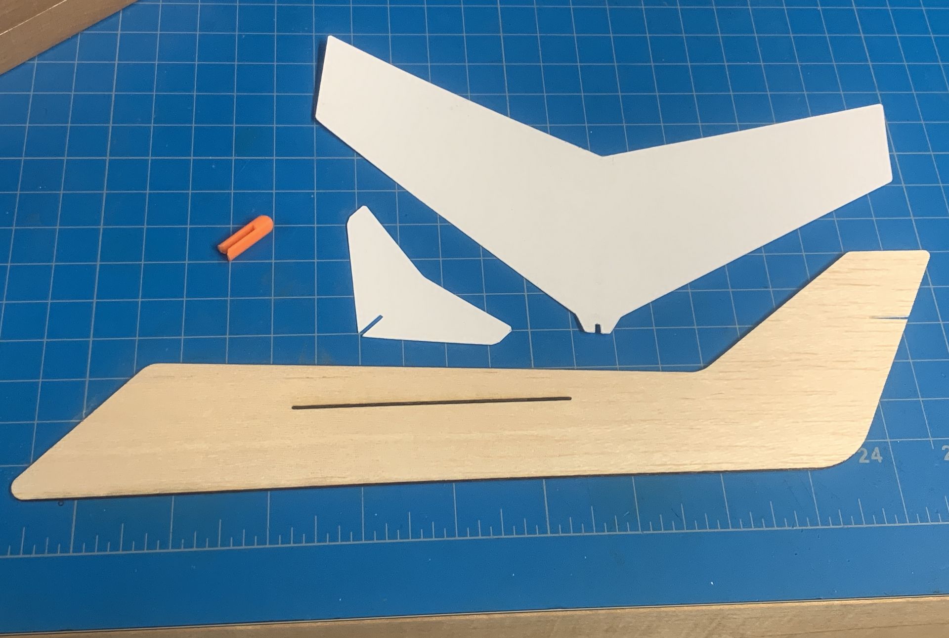
A. Slot finished pieces together:
A. Test it out: it's time to launch your plane!
B. Record your observations:
C. Repeat three times:
A. Make a design change:
B. Test your new glider:
C. Keep iterating:
A. Reflect & discuss:
B. Extend the learning:
Check out other fabricable projects - coming soon!
fiab@fabfoundation.org
Procurement
Deployment
Educational outreach
Made possible by generous support from: