Fab EDM
Thanks to Jakob Rockenberger who showed us that making your own EDM machine is possible during Fab Academy Instructor Bootcamp 2026 in Norway. Please find the experience documentation here.
Team
- Kris
- Henk
Background
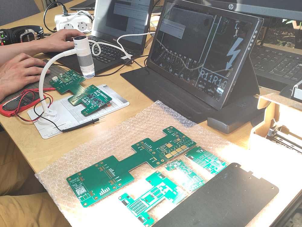
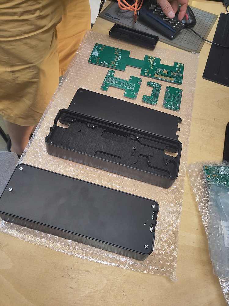
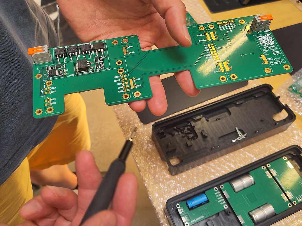
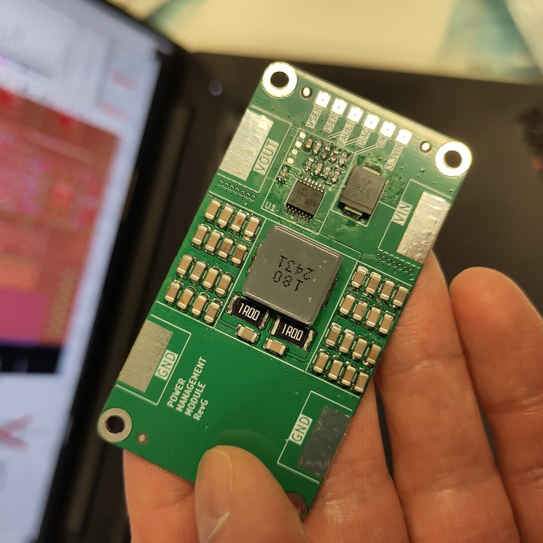
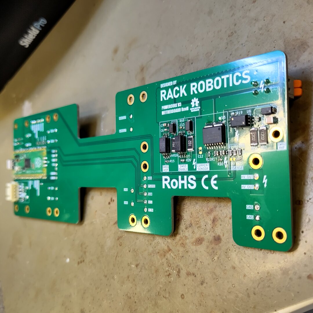
Parts to assemble the Rack Robotics PowerCore V3 (PCV3) EDM power supply were acquired between January and June 2026. A complete set of PCBs were populated with components.
 |
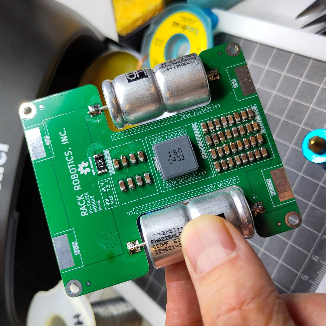 |
| Assembled Power Management module | Assembled Filter module |
 |
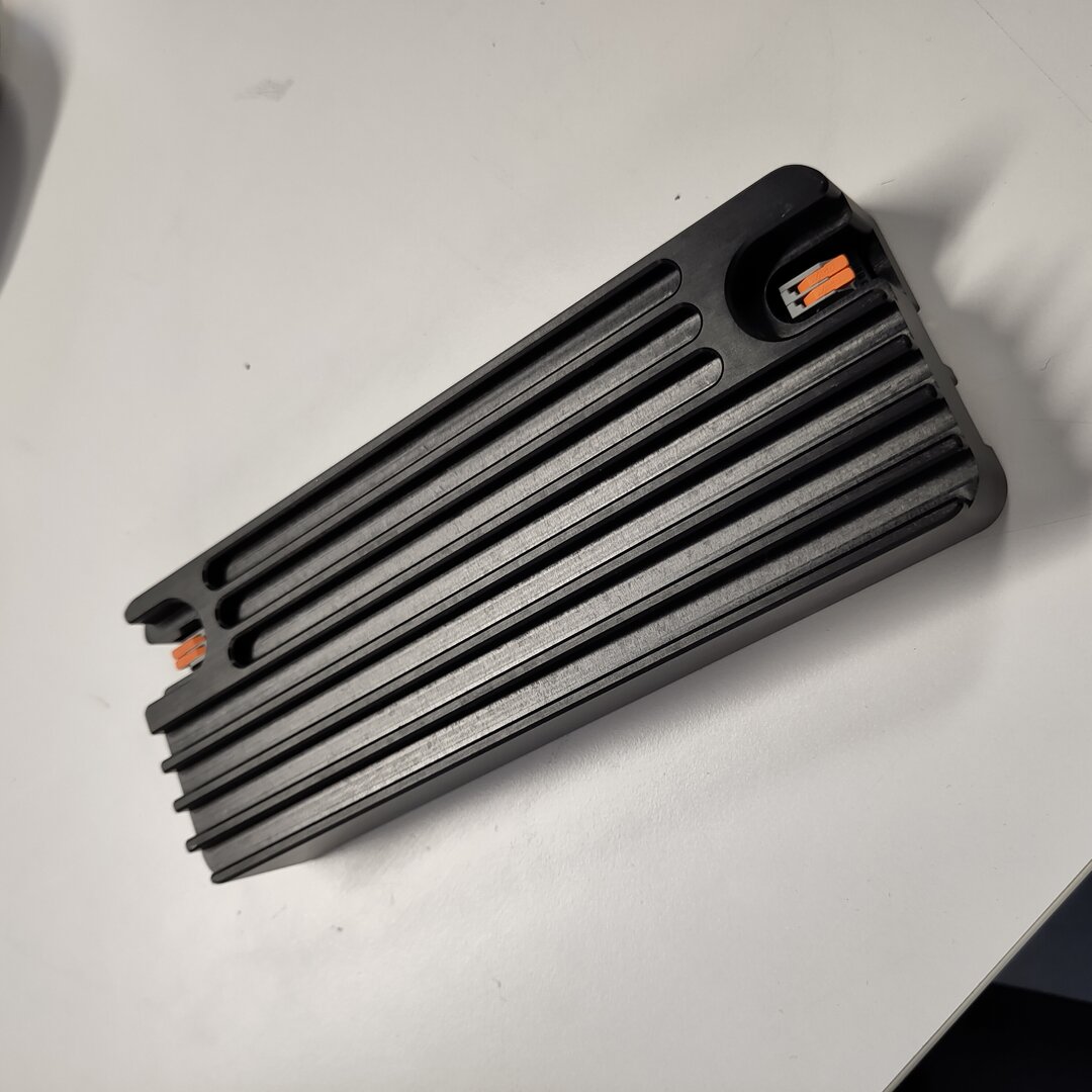 |
| Assembled Main module | All boards enclosed |
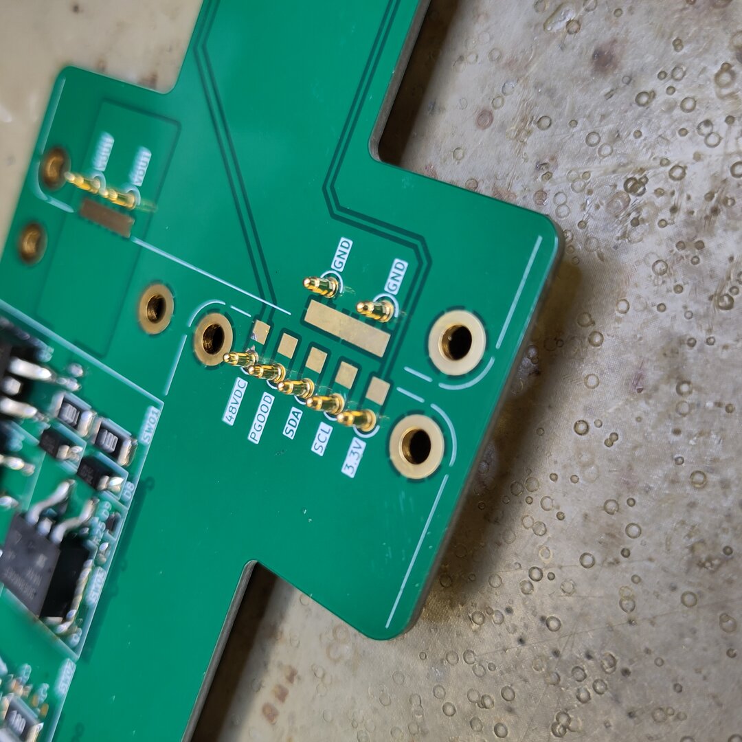
An interesting new thing was the use and soldering of spring-loaded or the so-called pogo pins. The way these were soldered was holding the pin in place with a finger and entering with a soldering iron that has a drop of solder on the tip from the other side. Pro tip: cover the finger with something heat resistant, but in a way it is still possible to feel the alignment of the pin.
 |
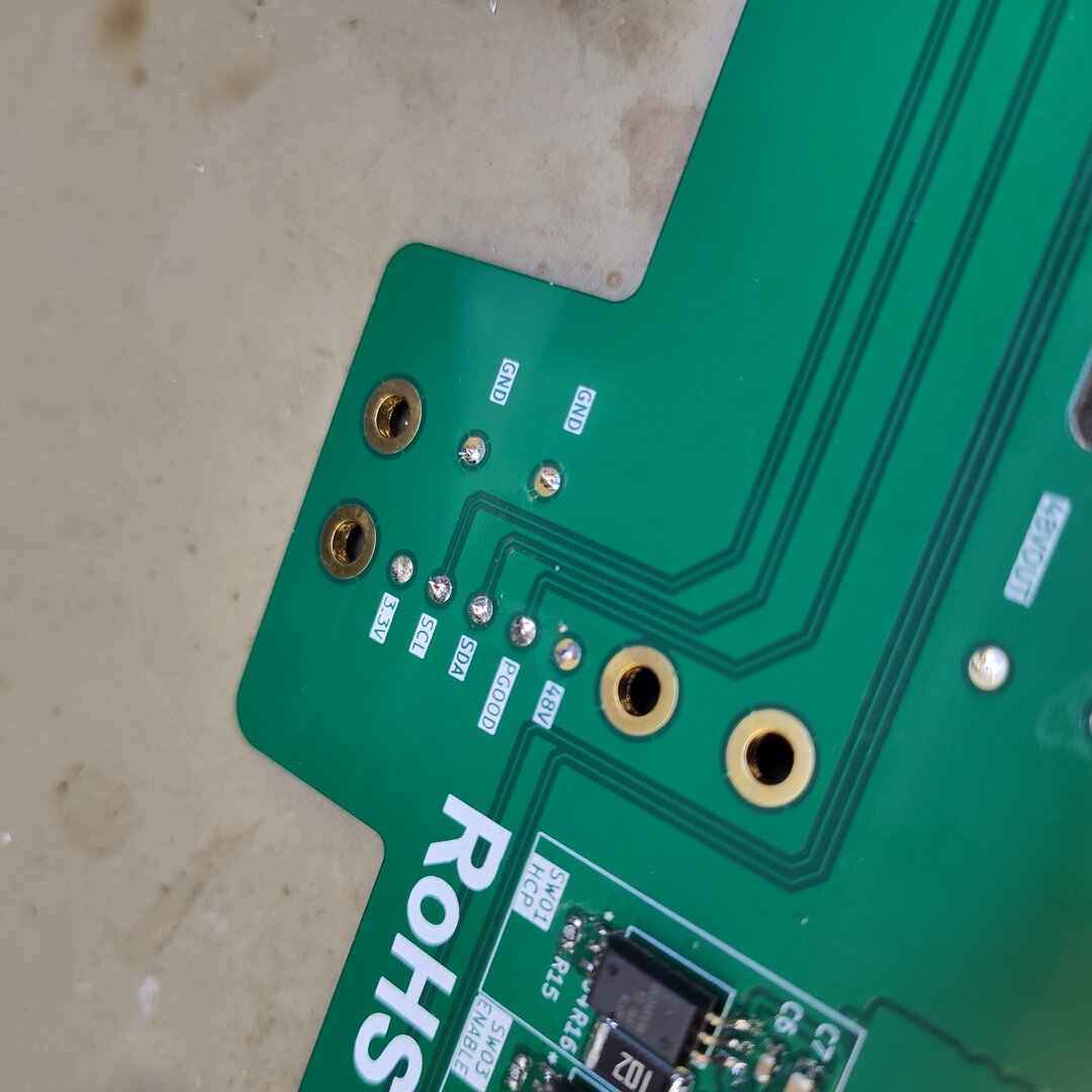 |
| Pogo pins on board (front) | Pogo pins on board (back) |
Bottrop Event Objectives
Bottrop event is therefore a great platform to perform a smoke test and hopefully move the project further from there. So here is a wishlist of accomplishments that we would like to achieve.
- Test the PowerCore
- Install firmware
- Test with power supply
- Verify oscilloscope readings
- Make some sparks
Process
Below is a honest and organic documentation of the steps we did while trying to target above mentioned objectives. Some time was spent re-reading the available documentation in the PowerCore GitHub repository. It is a dangerous device since it uses high voltage, thus the more one knows, the safer it is to work with it.
Flashing Firmware
PowerCore firmware comes as an .ino file, thus Arduino needs to be used to flash. arduino-cli was the choice this time as it is easier to document the process that way.
Step 1: Install Arduino CLI
Install arduino-cli. We used Arch Linux with sudo pacman -S arduino-cli). Using an alias is a small trick to go with, as retyping arduino-cli every time is a huge waste of time.
Step 2: Configure Arduino CLI
Configure arduino-cli and install additional cores and libraries. At the end of it you should see rp2040:rp2040 listed.
arduino-cli config init
arduino-cli config add board_manager.additional_urls https://github.com/earlephilhower/arduino-pico/releases/download/global/package_rp2040_index.json
arduino-cli core update-index
arduino-cli core install rp2040:rp2040
arduino-cli core list
Step 3: Fix PCV3 Firmware Folder
Arduino requires the .ino file to be in a directory with the same name. So once you are in the firmware directory (powercoreV3-firmware) use these commands to make it right.
mkdir -p powercore/
mv powercoreV3-firmware.ino powercore/powercore.ino   # names must match
Step 4: Compile Firmware
Run this command to compile the firmware without the board connected. This will demonstrate that your toolchain works and you can proceed with the uploading step.
arduino-cli compile --fqbn rp2040:rp2040:rpipico --output-dir ./build ./powercore
The command above should create a powercore.ino.uf2 file in the ./build directory.
Step 5: Upload Firmware
Connect your Pico which chould show up as a disk drive. Drag and drop the powercore.ino.uf2 file to the drive and reboot the Pico. If it did not work, download the compiled .uf2 file, based on the PowerCore firmware 1.1.0-beta source code.
Power Supply
First step was to find a compatible power supply. Rack Robotics PCV3 requires 48V >8A power supply. We were able to find two 24V ~9A power supplies, but one of them was not functional. Then we found a 48V 2A power supply and decided to move on with that for the test. The video below demonstrates that it did not work, but there was no smoke either.
This initial failure required a bit of head scratching, but later we discovered that one of the PCBs was inserted in the case the other way around. We flipped it, and managed to boot the PCV3 up.
Powering Up
The sequence is important as if things are done in the wrong order, the PCV3 will enter failure mode.
ENABLE_PIN: make sure you install a switch or jumper wire between ENA> BLE and 3.3V pins on the power input, USB, communication side.
- Connect the 48V power supply
- Flip the enable switch
- Connect via serial
You will be able to see the serial messages which will give you an idea of what is going on. We used picocom serial utility for serial connection.
picocom -b 115200 /dev/ttyACM0
Validating Oscillator Figures
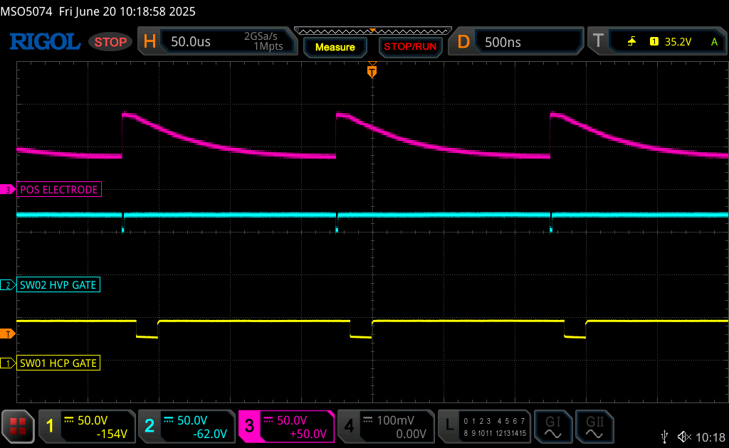
To confirm that the device is working, we decided to validate the gap voltage with electrodes separated as described in the original PCV3 GitHub repository. Below is an image with the red trace that we were looking forward to replicate.
A visit to local Lidl and toom Baumarkt was performed to acquire the following parts.
- Distilled water
- Wago connectors
- Euro box
- Welding sticks
- Some cables
A special electrode was made from solid core wires so that it can be easily bent into a shape where on one end the anode and cathode would be a few millimeters apart and the other end would be easy to handle and made for oscilloscope probe attachment.
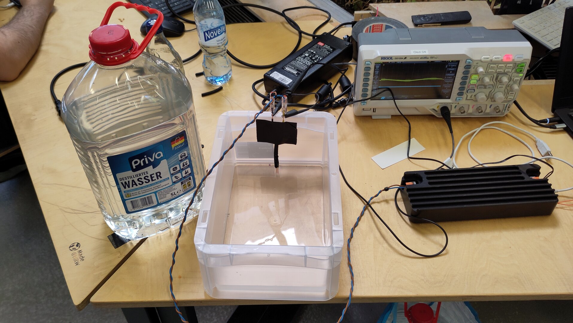
Some distilled water was poured into the box and electrodes dipped into it. The video below shows how it went.
First Sparks
In order to see the first sparks that look something like EDM cutting finally, a piece of aluminum was found and basic stabilizing clamps were 3D printed to keep the metal sheet some distance above the bottom of the box.
The idea was to use the Wago connector to hold the 1.5mm dia welding stick, but as it was not too stable, a 3D printable stabilizing attachment was designed to fix that.
Welding Stick Spec: 333 mm, 1.5 mm dia, CFH - G I / DIN 8554 Schweissklasse G I / EN 12536 : O I
The anode (+) of the system was connected to the material and the cathode (-) to the welding stick, as recommended by Rack Robotics Power Core V3 documentation. Default configuration (10k Hz machining freq, 10% duty cycle, 80V init voltage) was used for the test. Finally, the startup sequence was repeated and the it was tried to move the electrode towards the material slowly. There were sparks, but no signs of cutting yet.
Power Core Console
It was concluded that it would be good to have a better overview of the parameters and a convenient way of adjusting them. Therefore Claude AI Opus High Fast Mode was used to generate one based on the PowerCore V3 firmware. Claude scanned the firmware and created a browser-based app that would communicate with the PowerCode via WebSerial. The result is available as a repository on Kris's GitLab.
One would launch the console by running the serve.py python script. Claude made sure that it has some convenient user-friendly options. It launches the HTTP server and opens the console in default system browser automatically.
New Electrode
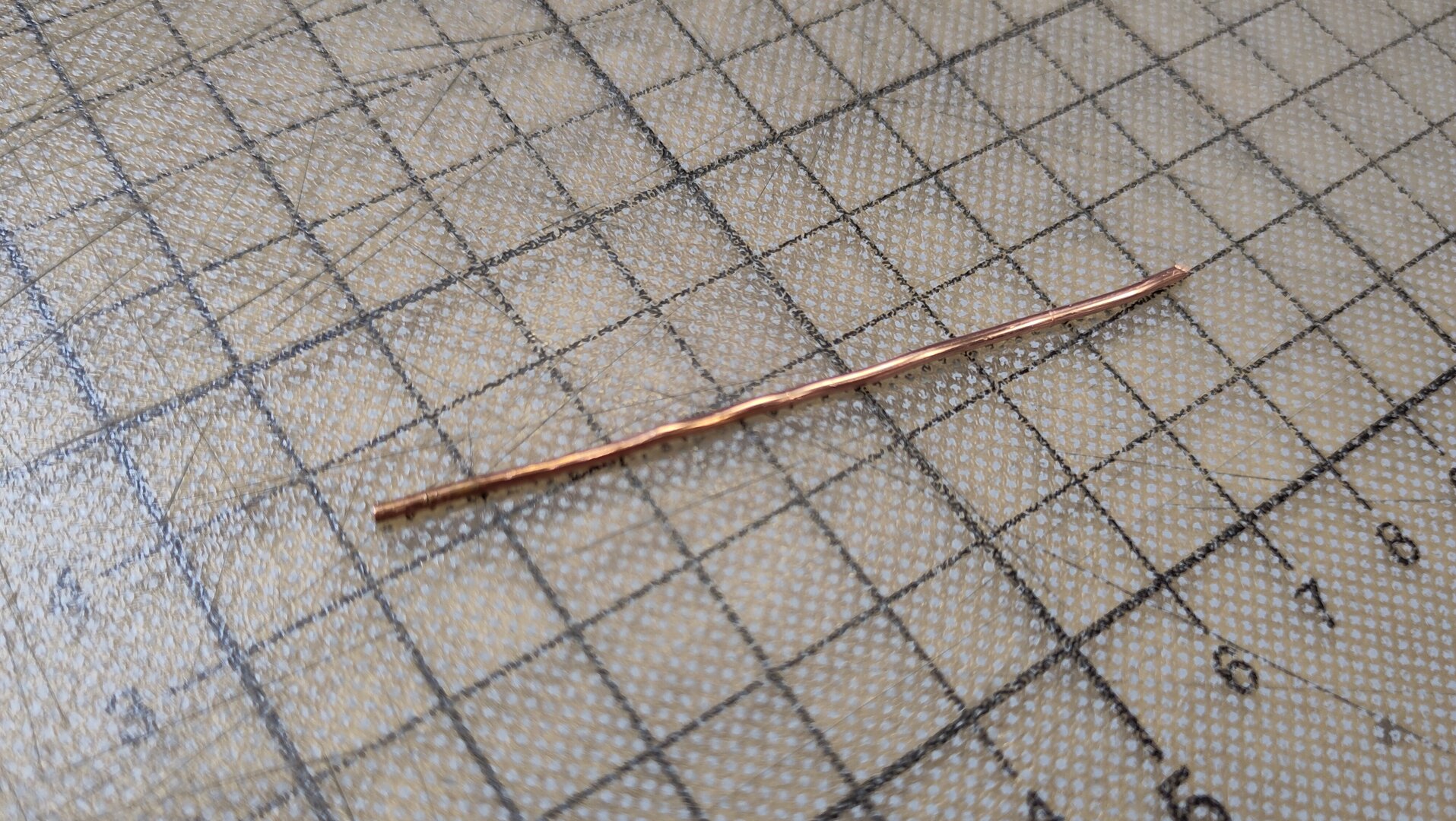
The sparks we got were not too consistent, and after a bit of reading it was found that that type of welding stick might not be the best choice for EDM. A brass or coper rod or tube would be a better choice instead. Therefore, we found a 1.35 mm solid core copper wire and made an electrode from it.
Improved Sparks
For the new Electrode, a new piece of material was found. A bit thinner sheet of aluminum. The same default ISO settings (10k Hz machining freq, 10% duty cycle, 80V init voltage) were used for the first test. You can see how it went in the edited video below.
Another test was performed with 5k Hz machining frequency, which was not much different.
Conclusions
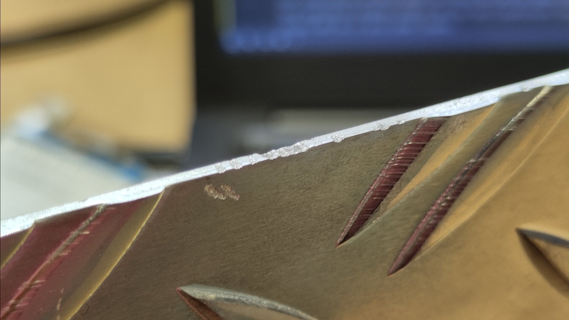
At this point it seems there is no fault in the provided open source files by Rack Robotics and it was possible to use them without modification. The assembled PowerCore passed the smoke test and generated sparks that were able to cut away some material from both sample pieces.
 |
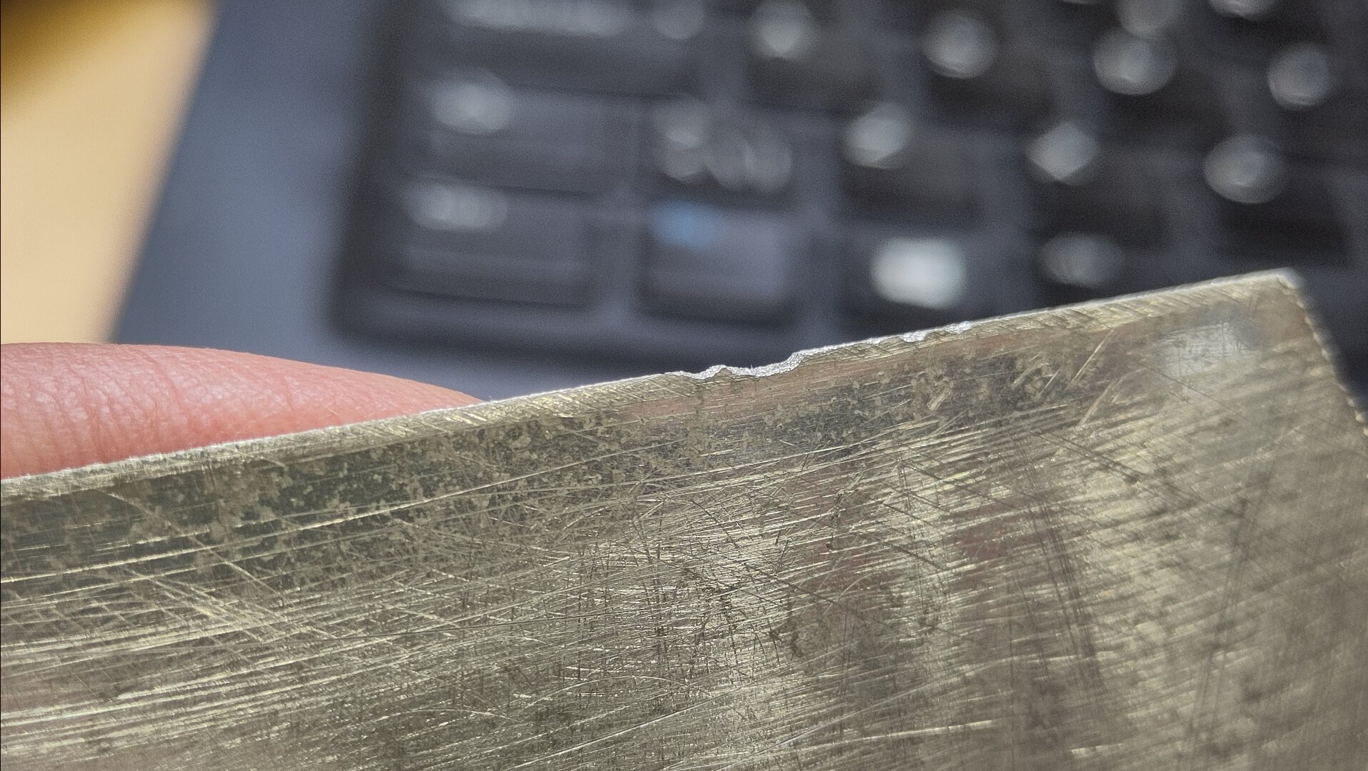 |
| Cut Sample A | Cut Sample B |
Our conclusions at this point are that the 48V 2A power supply is too slow to recharge the capacitors between cycles. So the next significant step is to hook the PCV3 to a proper 48V 8A or more power supply.
Photo from the audience